I really must find time to fix the old one, just in case.
Thursday, 20 December 2012
Pump controller update
A very quick update: The replacement pump controller is still behaving itself even though I know rain and splashed water does sit around it. Fingers-crossed the seals will hold up for a while yet.
Tuesday, 6 March 2012
Water water everywhere
So for the last week or so I've been running a bodged bypass cable, but I've not been happy risking it. After speaking to mate, I resigned myself to having to buy a replacement so I don't do more damage. At least it will allow me to investigate further without having to take the bike off the road.
New one arrived today from James Sherlock. The date on the bag said 20 Apr 2009! :-/
 |
| That's what £88 gets you! |
Heavy rain over the last couple of days meant the well around the pump connector was full of water and it had been running fine. Proof that, in the short term at least, water in the pump connector doesn't stop operation.
 |
| Now I just need some goldfish. |
 |
| Surprised it kept running at all! |
Interestingly, it seems that BMW have identified the same issue (that I mentioned in the first post) of water ingress via the base of the connector. So the new controller gets additional potting/sealing...
 |
| New controller with additional sealing around connector base. |
Tuesday, 28 February 2012
Quick update
Just a quick update: I'm running a bodged bypass lead for now as I have other things needing my attention. Once these are done I'll have another look at the circuit.
BTW, a female "Tamiya"/"Optimate" connector pushes in quite securely if you need to bodge a bypass adapter and can't use the original blue plug for whatever reason.
 |
| Maplin GZ99H |
Tuesday, 21 February 2012
One step closer
Well, I replaced the FET and cap, plugged it back in to the bike and... nothing. I'll admit I was disappointed. There was no voltage on the pump, meaning the FET was off. This can only be because it wasn't being driven, I knew the gate connection was sound, which only leaves the driver circuit.
To prove this, I tagged a resistor to the gate so that I could touch it to the incoming 12V and manually turn on the FET. Back on the bike, I cranked the engine and held the end of the resistor on the 12V pin (VGS max = 16V). After a while the engine fired up and ran as normal (it took some time to get the fuel through the system). So it's the driver circuit that's at fault...
Monday, 20 February 2012
Worth a try...
Jumped the break and threw it on the bike. It nearly fired... It was still without the cap too...
BMW R1200GS fuel pump controller
It's a known issue on certain bikes and mine has just died. I missed a rendezvous to ride out to Ace Cafe Adventure Day because of it! It was totally out of the blue; worked fine when I put it away and was dead when I went to use it 48hrs later. At least it didn't die at 70mph on a motorway!
I won't repeat the info that's on the forums and a particularly good site, motorcycleinfo.co.uk, but considering this issue is well known (as well as a work-around) I thought there must be a fix out there. Apparently not, at least, I couldn't find it.
So what are your options?
- Buy a replacement fuel pump controller (approx. £85 at time of writing).
- Bin the controller, after saving the connectors to make a bypass cable.
- Buy a pre-made bypass cable from forum members/eBay.
I didn't fancy #1, unless I really had to. #2 and #3 don't sit right with me, they'd be great as a get-you-home solution but BMW went to the time and expense of putting the controller in there; it has to be for a reason.
So I decided to open the thing up and take a look-see.
 |
| Scrape out the rubber potting compound and carefully prize out the board. |
 |
| I think the cap was fine before this. The connector snapped back together. |
The cap is a Rubycon 470uF 35V AL ZLH series capacitor rated for 105degC. It is AEC-Q101 qualified for automotive use and has a life of 10000 hours. As with all electrolytic caps, their life if significantly reduced if operated at high temperature. Could this be a cause of failures reported by many? Interestingly, there is a recess down in the heatsink area, made for a thermistor for monitoring temperature, that never made it into the final design?
 |
| Water seems to seep in through the base of the connector. |
Water marks and corrosion inside suggest water seeps in through the base of the connector. The seals on the mating half seal against the inside of the connector body, but water is free to sit against the base and can seep in under the rubber potting compound. The water itself won't really be a problem but the corrosion and contaminants would be.
 |
| Pretty cruddy! |
So I examined the circuit board and took the numbers of the power components (first suspects). What looks to be the power switching FET: 2N06607, the number was difficult to read but comes up as 17A 60V N-Channel logic FET, seems right to me. Next to it is a similar but smaller device: 12CWQ03FN, a 12A 30V dual common-cathode Schottky diode.
I ordered replacements for the cap (busted), FET (suspect) and diode (measured ok but I'm placing an order anyway). MOQ was 5 for the FET and diode and 10 for the cap. They should arrive tomorrow and we'll see what happens...
Meanwhile, whilst drawing out some of the circuit, I noticed that the FET had a lifted pad on the Gate lead! Trouble is I don't know if this is the root cause of the failure (mechanical stress from curing of potting compound or from vibration?) or if I did it when probing around.
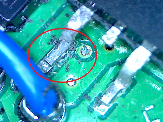 |
| Pad has lifted, but when? |
 |
| Pad and via is now open circuit. |
Subscribe to:
Posts (Atom)