Monday, 20 February 2012

BMW R1200GS fuel pump controller

It's a known issue on certain bikes and mine has just died. I missed a rendezvous to ride out to Ace Cafe Adventure Day because of it! It was totally out of the blue; worked fine when I put it away and was dead when I went to use it 48hrs later. At least it didn't die at 70mph on a motorway!

I won't repeat the info that's on the forums and a particularly good site, motorcycleinfo.co.uk, but considering this issue is well known (as well as a work-around) I thought there must be a fix out there. Apparently not, at least, I couldn't find it.

So what are your options?
  1. Buy a replacement fuel pump controller (approx. £85 at time of writing).
  2. Bin the controller, after saving the connectors to make a bypass cable.
  3. Buy a pre-made bypass cable from forum members/eBay.
I didn't fancy #1, unless I really had to. #2 and #3 don't sit right with me, they'd be great as a get-you-home solution but BMW went to the time and expense of putting the controller in there; it has to be for a reason.
So I decided to open the thing up and take a look-see.
Scrape out the rubber potting compound and carefully prize out the board.
With hindsight, the better way to do this is to de-solder the 3-pin connector and the electrolytic cap (which you don't know is there until you open it - now you know).
I think the cap was fine before this. The connector snapped back together.
The cap is a Rubycon 470uF 35V AL ZLH series capacitor rated for 105degC. It is AEC-Q101 qualified for automotive use and has a life of 10000 hours. As with all electrolytic caps, their life if significantly reduced if operated at high temperature. Could this be a cause of failures reported by many? Interestingly, there is a recess down in the heatsink area, made for a thermistor for monitoring temperature, that never made it into the final design?
Water seems to seep in through the base of the connector.
Water marks and corrosion inside suggest water seeps in through the base of the connector. The seals on the mating half seal against the inside of the connector body, but water is free to sit against the base and can seep in under the rubber potting compound. The water itself won't really be a problem but the corrosion and contaminants would be.
Pretty cruddy!

So I examined the circuit board and took the numbers of the power components (first suspects). What looks to be the power switching FET: 2N06607, the number was difficult to read but comes up as 17A 60V N-Channel logic FET, seems right to me. Next to it is a similar but smaller device: 12CWQ03FN, a 12A 30V dual common-cathode Schottky diode.

I ordered replacements for the cap (busted), FET (suspect) and diode (measured ok but I'm placing an order anyway). MOQ was 5 for the FET and diode and 10 for the cap. They should arrive tomorrow and we'll see what happens...

Meanwhile, whilst drawing out some of the circuit, I noticed that the FET had a lifted pad on the Gate lead! Trouble is I don't know if this is the root cause of the failure (mechanical stress from curing of potting compound or from vibration?) or if I did it when probing around. 
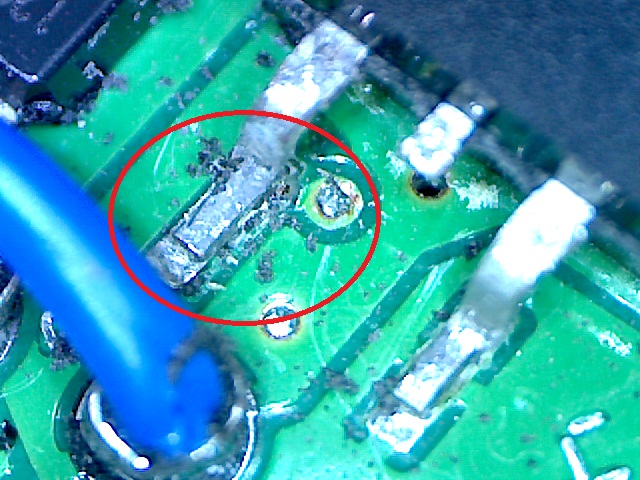
Pad has lifted, but when?
Pad and via is now open circuit.
It's getting late but I might just try repairing that...

Tuesday, 20 December 2011

New desk and resolutions

I built a new desk during some time off before starting a new job, although it's not quite finished, I did make it to my own requirements. Funny how I never expected to need room for three laptops and associated crap, but I did today when I spent the day working from home...

Never enough room?
A New Years resolution? To update my blog(s) more, try to do some more work on my UAV thing and projects generally (better balance with family/bike/studies). I've left most of the bike stuff at Adventure Bike Rider forum and not posted much here, but that may change depending how I feel...

Sunday, 2 October 2011

I haven't been idle

Stripped to replace the headstock bearing,

Sorted, rebuilt and added a rad protector too :-) 

Wednesday, 7 September 2011

Been busy, but not on projects...

I took my bike off road for the first time in early December, and fell off in the mud. First tried motorcycle camping in late December then a bike rally in April. Lots of green lanes since then and even a river crossing. More recently I've done some servicing and maintenance and then some more riding :-)
On top of the all-consuming motorcycling, a huge chunk of my time and energy goes on my studies. I'm on year four of four (part-time). And I manage to squeeze in some gaming (GEARS OF WAR!!!) around family stuff too.
Sometimes I spend a few hours on a project, usually late on into the wee hours, often with loud music on to help keep me focused/awake. I had a FINALLY! moment, despite hopeless (LCD) datasheets, I finally got round to trying out a standard LCD. I love Microchip PICmicros!
Finally! Late nights and loud music win again despite hopeless (LCD) datasheets.

Wednesday, 10 November 2010

iPhone mount (again)

Finally pulled my finger out and sorted my iPhone mount on my bike. I went about a week before pulling it off again and attempting to get a charger in to the waterproof case ("iDry" from Amazon/eBay) as well.

Modified iDry case on BMW GSA.
On-bike view. I use Tom-Tom and MotionX GPS apps.
Protected from the worst of the elements by the screen.
The same mount as before - can be vertical or horizontal.
Cheapo charger bought mainly for cable and connector.
I cut a slot in the inside wall (double wall at bottom) with my Dremel clone. I dismantled the connector and moved the PCB on to short flying leads to allow me to glue the connector in the slot I just made. The PCB sits at a right-angle in the small cavity were the hinge pin sits. Cable entry strain relief, PCB and iPhone connector are all fixed and sealed with hot-melt glue. The particular glue I have remains rubbery and allows the connector to move slightly as I fit or remove my iPhone.

Original cable grommet was used, but it was cheap and split almost immediately.
Standard car power socket spliced into aux power socket (for flexibility).
I spliced a cable mount accessory socket (which I already had in my collection of crap) on to the bike's power socket, which stays on for 5 minutes after key-off. I could have hard-wired it but this gives me more options.

The original iPhone charger I used was one of two (one in the car) cheapo chargers from Amazon. It stopped charging after a couple of rides. Testing showed the DC-DC converter inside didn't seem to always start up correctly. Through this, I found that the iPhone 3G is 12V tolerant - it is protected against having 12-odd volts connected to it's power pins!

I bought another generic phone charger (I already had the connector) from Tesco late one evening. It was rated at 5V 500mA, great, that should do it. After another couple of rides it too was dead. Further testing (which I should have done to begin with) showed that with Sat-Nav running and playing music over Bluetooth; the iPhone 3G was pulling up to 800mA. No wonder the cheap chargers aren't up to it.

I was looking through my parts looking for a LM7805 or similar, I was going to make up a small board. I then came across a small Traco DC-DC converter which I'd forgotten I had. Checking the datasheet; it has a wide input voltage range and adjustable output voltage and current up to 2A! It even has a enable line. Perfect.

I added some caps, as per the datasheet and re-used one of the cheapo housings to keep it together. Plenty of "anti-vibration" hot-melt to keep it from falling apart and the job's a good 'un.

Phone now charges from flat even if in heavy use. I'm a happy chappy.

The bike rocks, BTW. ;-)

Saturday, 18 September 2010

New bike, new possibilities

I've got myself a BMW R1200GS Adventure! I'm due to pick it up on Wednesday and can't wait!

I've already got a project in mind for it; a little electronics add-on...
And I'll have space for my iPhone/SatNav now too :-)

An awesome piece of engineering.

Wednesday, 8 September 2010

Portable Workspace

Saw this on Make:
http://blog.makezine.com/archive/2010/09/portable_electronics_desk.html
...and it looks amazingly similar to mine, but I cheated; using a existing case. Note the LED work light (telescopic fold-away), old computer PSU from my collection of crap and a battery powered soldering iron (OK for light duty work). This is a pic of me using it at Super Happy Dev Club meet #17.
Portable workspace at SHDC #17.